
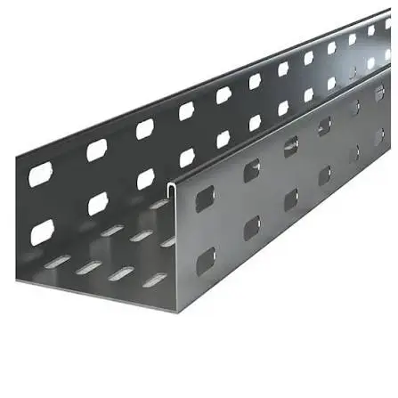
Cable tray systems have become an essential part of modern commercial and industrial electrical infrastructure. From hospitals and data centers to manufacturing plants and airports, these systems provide an efficient method for supporting and organizing power, communication, and control cables while allowing flexibility for future expansion and maintenance. Compared with traditional conduit systems, cable trays simplify cable routing, reduce installation time, and improve accessibility throughout the life of a facility.
As building systems become increasingly complex, cable tray design extends far beyond selecting a tray type. Engineers and contractors must consider structural loading, support spacing, seismic forces, thermal expansion, grounding, corrosion resistance, and coordination with mechanical and plumbing systems. Electrical installations must also comply with the National Electrical Code (NEC), while structural support systems often require compliance with the International Building Code (IBC), California Building Code (CBC), and ASCE 7 for seismic design.
Projects located in high seismic regions, particularly throughout California and the western United States, require additional engineering consideration. Cable tray support systems frequently require engineered seismic bracing to help maintain electrical service during seismic events while protecting occupants and critical infrastructure. Healthcare facilities and other essential buildings may also require compliance with HCAI (formerly OSHPD) requirements, making engineering documentation and code coordination an important part of project delivery.
This guide explains how cable tray systems are designed, supported, installed, and integrated into modern MEP infrastructure. It explores tray types, material selection, structural support systems, seismic bracing requirements, installation best practices, and applicable engineering standards. Whether you are a structural engineer, electrical engineer, MEP contractor, architect, facility manager, or project manager, understanding these principles helps improve constructability, code compliance, long-term reliability, and lifecycle performance.
What Is a Cable Tray System?
A cable tray system is a structural support system designed to safely carry insulated electrical cables used for power distribution, communication networks, fire alarm circuits, automation controls, and data transmission throughout a building or industrial facility. Instead of enclosing every conductor within conduit, cable trays provide an open support method that simplifies installation while allowing easier inspection, maintenance, and future system modifications.
Cable trays are widely used in commercial buildings, industrial facilities, healthcare campuses, data centers, airports, universities, manufacturing plants, and utility infrastructure because they provide flexibility without sacrificing organization or safety. Large electrical projects often contain thousands of feet of cable serving equipment located throughout multiple floors and mechanical spaces. Cable tray systems help organize these cables into structured pathways while maintaining accessibility.
Purpose in Modern Electrical Infrastructure
Modern facilities rely on numerous electrical systems operating simultaneously. Power feeders, branch circuits, fiber optic cables, communication wiring, building automation networks, emergency systems, and security infrastructure all require organized routing.
Cable tray systems support these diverse electrical services by:
- Providing continuous cable pathways
- Reducing cable congestion
- Improving maintenance access
- Supporting future expansion
- Simplifying troubleshooting
- Enhancing project constructability
Because trays remain accessible after installation, facility personnel can add or replace cables with significantly less disruption than enclosed conduit systems.
How Cable Trays Differ from Conduit Systems
Although conduit provides superior physical protection for individual conductors, it requires each circuit to be pulled through enclosed raceways. Cable trays instead create open structural pathways capable of supporting multiple cable types simultaneously.
For larger commercial projects, this difference translates into:
- Lower labor requirements
- Faster installation
- Easier inspection
- Simplified modifications
- Reduced long-term maintenance costs
Engineers often specify both conduit and cable trays within the same facility depending on environmental conditions, occupancy requirements, and cable type.
Common Commercial and Industrial Applications
Cable tray systems are commonly installed in:
- Hospitals
- Data centers
- Manufacturing facilities
- Pharmaceutical plants
- Airports
- Warehouses
- Water treatment facilities
- Power generation plants
- Commercial office buildings
- Higher education campuses
These facilities frequently contain extensive MEP infrastructure where organized cable management improves safety, maintenance efficiency, and future scalability.
Types of Cable Tray Systems
Selecting the appropriate cable tray begins with understanding the operational environment, cable type, loading conditions, ventilation requirements, and maintenance expectations. No single tray configuration is ideal for every project, which is why engineers evaluate mechanical performance alongside electrical and structural considerations.
Ladder Cable Tray
Ladder cable trays are among the most commonly specified systems in commercial and industrial construction. Two longitudinal side rails connected by transverse rungs create an open ladder-like structure that offers excellent ventilation while minimizing weight.
Advantages include:
- High load capacity
- Excellent heat dissipation
- Easy cable entry and exit
- Reduced cable overheating
- Long-span capability
- Efficient support of large power cables
Ladder trays are frequently installed within industrial plants, manufacturing facilities, utility tunnels, and large electrical rooms where airflow and accessibility are priorities.
Perforated Cable Tray
Perforated trays feature a continuous bottom with regularly spaced openings that provide moderate ventilation while offering increased support for smaller cables.
These trays are often selected for:
- Commercial buildings
- Office developments
- Educational facilities
- Healthcare environments
- Mixed power and communication systems
The perforated design offers improved support for smaller diameter conductors while still allowing airflow and drainage.
Solid-Bottom Cable Tray
Solid-bottom trays completely enclose the bottom surface, providing greater protection against dust, debris, and electromagnetic interference in certain applications.
They are commonly used where:
- Sensitive communication cables are present
- Environmental contamination is a concern
- Additional cable protection is desired
- Indoor clean environments require enclosed pathways
Because ventilation is reduced, engineers must carefully evaluate cable ampacity and heat buildup.
Wire Mesh Cable Tray
Wire mesh cable trays, sometimes called basket trays, have become increasingly popular for communication infrastructure and low-voltage systems.
Benefits include:
- Lightweight construction
- Fast installation
- Easy field modifications
- Excellent airflow
- Flexible routing
- Cost-effective installation
These systems are widely used within data centers, office buildings, laboratories, and technology facilities where frequent cable additions occur.
Trough Cable Tray
Trough trays combine characteristics of ladder and solid-bottom systems by providing a partially enclosed structure that offers greater cable support while maintaining some ventilation.
Applications include:
- Control wiring
- Instrumentation
- Industrial automation
- Mixed electrical systems
Selecting the Right Tray for Different Environments
Selecting the appropriate tray involves evaluating:
- Cable weight
- Span length
- Environmental exposure
- Corrosion risk
- Ventilation requirements
- Future expansion
- Fire protection requirements
- Structural loading
- Maintenance accessibility
Electrical engineers coordinate these factors with structural engineers to ensure the support system safely transfers loads into the building structure without exceeding allowable capacities.
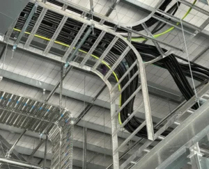
Cable Tray System
Cable Tray Materials and Corrosion Protection
Material selection significantly affects the durability, maintenance requirements, structural capacity, and lifecycle cost of a cable tray system. Engineers evaluate environmental exposure, humidity, chemical contamination, coastal conditions, and project budget before specifying materials.
Hot-Dip Galvanized Steel
Hot-dip galvanized steel remains one of the most common materials for commercial construction. After fabrication, steel components receive a zinc coating that provides long-term corrosion resistance.
Advantages include:
- Excellent structural strength
- Proven durability
- Cost-effective performance
- Suitable for outdoor installations
- Long service life
This material is frequently used in manufacturing plants, utility facilities, and exterior installations.
Pre-Galvanized Steel
Pre-galvanized steel receives its protective coating before fabrication. While economical for indoor applications, cut edges may require additional corrosion protection depending on the environment.
It is commonly specified for:
- Office buildings
- Schools
- Retail facilities
- Interior mechanical rooms
Aluminum
Aluminum cable trays offer an excellent strength-to-weight ratio while naturally resisting corrosion.
Benefits include:
- Lightweight installation
- Reduced structural dead load
- Excellent corrosion resistance
- Easy handling
- Lower transportation costs
Aluminum is widely used in wastewater treatment plants, coastal facilities, food processing plants, and rooftop installations where corrosion exposure is elevated.
Stainless Steel
Stainless steel provides exceptional resistance to moisture, chemicals, and harsh industrial environments.
Common applications include:
- Pharmaceutical manufacturing
- Food processing
- Chemical plants
- Marine facilities
- Cleanrooms
- Healthcare environments
Although stainless steel has a higher initial cost, its durability often reduces long-term maintenance expenses.
Fiberglass Reinforced Plastic (FRP)
FRP cable trays provide excellent corrosion resistance while remaining electrically nonconductive.
These systems perform well in aggressive environments where traditional metals may deteriorate due to chemical exposure or moisture.
Protective Coatings for Corrosive Environments
Beyond material selection, protective finishes further improve service life.
Common options include:
- Powder coating
- Epoxy coatings
- PVC coatings
- Zinc-rich finishes
- Specialized corrosion-resistant systems
Facilities located near coastlines, wastewater treatment plants, chemical processing operations, or industrial manufacturing sites often require enhanced corrosion protection to maximize system longevity while minimizing maintenance requirements.
Cable Tray Support Systems and Structural Design
A cable tray is only as reliable as the support system beneath it. While the tray carries electrical cables, the structural support system transfers dead loads, live loads, seismic forces, and in some cases wind loads into the building structure. Poorly designed supports can lead to excessive deflection, damaged cables, failed anchors, or even collapse during extreme loading events. For this reason, cable tray support systems should be engineered as part of the overall structural and MEP coordination process rather than treated as an afterthought.
Support selection depends on numerous variables, including tray width, cable weight, span length, ceiling height, building structure, seismic design category, maintenance accessibility, and future expansion. Commercial projects often require thousands of individual support components that must work together as an integrated structural system.
Strut Channel Systems
Strut channel systems form the backbone of many cable tray installations because they offer exceptional flexibility and modularity. Available in various sizes and finishes, strut channels can be field-adjusted while accommodating changes during construction.
Typical applications include:
- Horizontal tray supports
- Multi-tier cable tray racks
- Equipment framing
- Combination supports for cable trays, conduit, and piping
- Rooftop utility structures
Custom-fabricated strut assemblies can also simplify installation on complex projects where standard configurations are insufficient.
Trapeze Hangers
Trapeze hangers are among the most common support methods for suspended cable trays. They typically consist of transverse strut channels suspended by threaded rod assemblies attached to structural steel or concrete above.
Advantages include:
- Uniform load distribution
- Excellent accessibility
- Simple future modifications
- Support for multiple tray levels
- Efficient installation over long corridors
Proper sizing of threaded rods, channel sections, and connections is critical to prevent excessive deflection.
Cantilever Brackets
Wall-mounted cantilever brackets eliminate the need for ceiling supports where structural walls are available. These brackets are particularly useful in electrical rooms, utility tunnels, and equipment spaces.
Engineers evaluate:
- Wall capacity
- Anchor type
- Eccentric loading
- Tray width
- Cable weight
Proper anchor design is especially important for concrete and masonry installations.
Wall-Mounted and Ceiling-Mounted Supports
Both wall-mounted and ceiling-mounted systems are selected based on architectural constraints, structural framing, and maintenance access.
Ceiling-mounted supports are common in:
- Data centers
- Hospitals
- Commercial offices
- Manufacturing facilities
Wall-mounted systems often improve access where ceiling congestion limits available space.
Threaded Rod Assemblies
Threaded rods transfer tray loads into overhead framing while allowing installers to adjust elevations during construction.
Common considerations include:
- Rod diameter
- Buckling resistance
- Corrosion protection
- Load capacity
- Seismic performance
Engineers frequently specify galvanized or stainless steel threaded rods depending on environmental conditions.
Anchor Selection
Anchors represent one of the most critical components of any support system. Their performance directly affects structural reliability during both normal operation and seismic events.
Anchor selection depends upon:
- Concrete strength
- Existing reinforcement
- Edge distance
- Embedment depth
- Expected loading
- Seismic qualification
Post-installed anchors used in seismic applications should comply with applicable ICC-ES evaluation reports and manufacturer installation requirements. Proper installation torque and inspection are equally important for long-term performance.
Seismic Cable Tray Bracing Requirements
In regions subject to seismic activity, cable tray systems require more than conventional gravity supports. Earthquakes generate lateral and vertical accelerations that can cause unsupported electrical systems to sway, collide with adjacent building components, or fail completely. Seismic cable tray bracing helps maintain system integrity, protects occupants, and supports continued building operation after an earthquake.
For essential facilities—including hospitals, emergency operations centers, and critical infrastructure—the performance of cable tray systems can directly affect life safety and operational continuity.
Why Seismic Restraint Is Required
Unlike static gravity loads, earthquakes introduce rapidly changing dynamic forces. Even relatively lightweight cable trays can generate significant inertial forces when fully loaded with electrical conductors.
Without proper restraint, cable trays may experience:
- Excessive lateral movement
- Support failure
- Anchor pullout
- Damage to electrical cables
- Equipment disconnection
- Interference with adjacent MEP systems
Seismic restraint minimizes these risks by limiting movement while transferring earthquake forces safely into the building structure.
ASCE 7 Seismic Considerations
ASCE 7 establishes the structural loading criteria used throughout the United States for seismic design. Cable tray support systems must be evaluated based on several project-specific factors, including:
- Seismic Design Category
- Component importance
- Occupancy classification
- Building height
- Spectral response acceleration
- Component weight
- Attachment details
Engineered seismic calculations determine brace spacing, support sizing, anchor selection, and force distribution throughout the system.
Transverse and Longitudinal Bracing
Effective seismic restraint generally requires resistance in multiple directions.
Transverse bracing controls movement perpendicular to the tray run, while longitudinal bracing limits movement parallel to the tray.
These braces commonly incorporate:
- Structural steel angles
- Strut channels
- Diagonal members
- Beam clamps
- Seismic connectors
- Rated anchors
The configuration depends upon tray geometry and structural framing.
Support Spacing
Support spacing influences both gravity performance and seismic behavior.
Factors affecting spacing include:
- Tray width
- Cable weight
- Structural capacity
- Tray material
- Seismic forces
- Manufacturer recommendations
Longer spans reduce support quantity but increase structural demands. Engineers balance efficiency with allowable deflection and seismic performance.
Expansion Joints
Large buildings experience thermal movement and differential structural displacement. Expansion splice assemblies allow cable trays to accommodate these movements without overstressing connections.
Expansion joints become particularly important where trays cross:
- Building expansion joints
- Seismic separation joints
- Long corridors
- Elevated bridges
Proper detailing prevents unintended restraint while maintaining electrical continuity.
Healthcare and Essential Facilities
Hospitals often impose some of the most demanding seismic performance requirements because electrical systems support life safety equipment, operating rooms, imaging devices, emergency power systems, and critical communications.
Projects governed by HCAI requirements typically require comprehensive engineering documentation, detailed seismic calculations, approved support assemblies, and rigorous inspection procedures. Early coordination among structural engineers, electrical designers, contractors, and specialty fabricators helps reduce construction delays while supporting compliance.
Electrical Design Considerations
Although cable trays primarily serve as structural support systems, electrical performance remains the driving factor behind their design. Engineers must ensure that cable trays safely support electrical conductors while maintaining acceptable operating temperatures, minimizing electromagnetic interference, and providing sufficient capacity for future building expansion.
Successful designs balance structural efficiency with electrical reliability.
Cable Fill Capacity
One of the first design considerations involves determining allowable cable fill.
Excessive cable fill can:
- Restrict airflow
- Increase conductor temperature
- Complicate maintenance
- Limit future expansion
- Increase pulling difficulty
NEC provisions establish allowable fill criteria based on cable type and installation method. Engineers should avoid designing systems that immediately approach maximum capacity.
Power Versus Communication Cables
Modern buildings contain numerous cable types serving different purposes.
These include:
- Medium-voltage feeders
- Low-voltage power
- Fire alarm systems
- Fiber optics
- Data networks
- Security systems
- Building automation
- Process control
Where appropriate, engineers separate communication and power cables to reduce electromagnetic interference while improving maintenance efficiency.
Grounding and Bonding
Because metallic cable trays can become energized under fault conditions, grounding and bonding represent essential safety requirements.
Proper grounding helps:
- Protect personnel
- Reduce shock hazards
- Improve fault current paths
- Support overcurrent device operation
- Maintain electrical continuity
Grounding methods should comply with NEC requirements and project specifications.
Thermal Expansion
Temperature changes cause both trays and supporting structures to expand and contract.
Engineers evaluate:
- Material properties
- Expected temperature range
- Tray length
- Expansion splice locations
- Structural movement
Failure to accommodate thermal movement may overstress supports and tray connections.
Future Capacity Planning
Electrical infrastructure rarely remains static throughout a building’s life.
Data centers expand.
Manufacturing equipment changes.
Hospitals install new imaging systems.
Commercial tenants modify office layouts.
Designing cable tray systems with additional capacity allows facilities to accommodate future growth without major reconstruction. Engineers frequently reserve spare tray space or include additional support capacity for anticipated expansion.
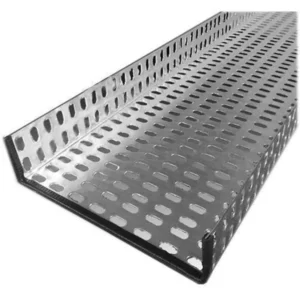
Cable Tray System
NEC, NEMA and Building Code Requirements
Code compliance forms the foundation of every cable tray installation. While manufacturers provide product-specific guidance, designers must ensure the complete system—including trays, supports, anchors, grounding, and seismic bracing—meets applicable national, state, and local requirements.
Understanding how various standards work together improves both project quality and inspection readiness.
NEC (NFPA 70)
The National Electrical Code establishes installation requirements for electrical systems throughout the United States.
For cable trays, the NEC addresses topics such as:
- Permitted cable types
- Cable fill
- Support requirements
- Grounding and bonding
- Installation methods
- Maintenance access
Electrical engineers and contractors should always verify that installations satisfy the latest adopted code edition.
NEMA VE 1
NEMA VE 1 establishes manufacturing requirements for metal cable tray systems.
It addresses:
- Structural performance
- Dimensions
- Material quality
- Load testing
- Product ratings
Using products manufactured to recognized industry standards helps improve consistency across projects.
NEMA VE 2
NEMA VE 2 provides practical installation guidance covering support spacing, field modifications, splice installation, and recommended construction practices.
Many contractors use these recommendations during installation planning and quality control.
IBC and CBC
The International Building Code and California Building Code govern structural safety, including nonstructural components such as cable tray support systems.
Where seismic design applies, these codes work together with ASCE 7 to establish engineering requirements for restraint, anchorage, and structural performance.
HCAI Requirements
Healthcare construction projects often require additional documentation and engineering review beyond conventional commercial buildings.
Cable tray systems supporting essential electrical services may require:
- Engineered seismic calculations
- Approved support assemblies
- Inspection documentation
- Coordination with hospital operational requirements
UL Listed Systems
Certain applications require UL Listed or UL Classified components depending on fire resistance, electrical safety, or project specifications.
Design professionals should verify listing requirements early in the project to avoid procurement or inspection delays.
Cable Tray Installation Best Practices
Even the best-engineered cable tray system can underperform if installation quality does not match the design intent. Successful installations begin long before the first support is mounted. Proper planning, field coordination, and quality control help reduce rework, improve constructability, and ensure long-term system reliability.
Layout Planning
A coordinated cable tray layout minimizes conflicts with structural framing, HVAC ductwork, fire protection piping, plumbing, and architectural elements. On complex projects, cable tray routing should be coordinated during the design phase using Building Information Modeling (BIM) to identify clashes before construction begins.
Engineers should evaluate:
- Structural attachment locations
- Required clearances for maintenance
- Future cable additions
- Access to electrical equipment
- Fire-rated wall and floor penetrations
- Building expansion joints
Proper planning also simplifies inspections and future facility modifications.
Support Spacing
Support spacing should follow engineered calculations, manufacturer recommendations, and applicable code requirements. Factors affecting spacing include tray width, cable weight, material type, environmental loading, and seismic design requirements.
Supports should be positioned to minimize deflection while maintaining alignment across long cable runs. Additional supports may be required near changes in direction, expansion joints, or concentrated equipment loads.
Splice Connections
Tray splice plates must be installed according to manufacturer requirements using the specified hardware and tightening procedures. Misaligned or improperly tightened splice connections can reduce structural capacity and increase maintenance concerns.
Expansion splice assemblies should be installed where thermal movement or structural displacement is anticipated.
Cable Routing
Good cable management practices reduce stress on conductors and improve long-term serviceability.
Installers should avoid:
- Excessive cable stacking
- Tight bend radii
- Overloaded tray sections
- Sharp edges
- Unsupported cable drops
Proper cable separation also reduces electromagnetic interference between power, communication, and instrumentation systems.
Inspection Checklist
Before project turnover, engineers and inspectors typically verify:
- Tray alignment
- Support spacing
- Anchor installation
- Grounding and bonding
- Splice integrity
- Seismic bracing
- Cable fill compliance
- Identification labeling
- Corrosion protection
- Overall workmanship
Early quality control reduces costly corrections during final inspections.
Common Installation Mistakes
Some of the most common field issues include:
- Oversized support spacing
- Incorrect anchor installation
- Missing seismic restraints
- Poor grounding continuity
- Inadequate expansion provisions
- Unsupported cable transitions
- Improper tray loading
- Lack of coordination with other MEP trades
Avoiding these issues improves both safety and long-term reliability.
Cable Tray Systems in Commercial and Industrial Facilities
Cable tray systems are used in nearly every major construction sector because they provide scalable, maintainable infrastructure for electrical distribution. However, each facility type presents unique operational requirements that influence tray selection, support design, and installation methods.
Hospitals
Healthcare facilities rely on continuous electrical service for life safety systems, diagnostic imaging, surgical suites, patient care equipment, and emergency power distribution.
Cable tray systems in hospitals often require:
- Engineered seismic restraint
- Redundant power routing
- Coordination with medical gas systems
- Compliance with HCAI requirements
- High levels of documentation and inspection
Reliability and maintainability are often prioritized alongside constructability.
Data Centers
Data centers contain dense electrical and communication infrastructure supporting servers, storage equipment, networking hardware, and backup power systems.
Cable trays help organize:
- Fiber optic cables
- Power distribution
- UPS connections
- Network infrastructure
- Building monitoring systems
Well-designed tray systems also simplify future expansion without disrupting operations.
Manufacturing Plants
Industrial facilities frequently support heavy power distribution, automated production lines, robotics, and process control systems.
Cable trays provide flexibility for:
- Equipment upgrades
- Production line modifications
- Additional instrumentation
- Process expansion
Durable materials and corrosion-resistant finishes are commonly specified in demanding industrial environments.
Airports
Airport facilities require extensive electrical infrastructure supporting lighting, communications, security, baggage handling, and transportation systems.
Cable tray systems improve accessibility while accommodating future operational changes within complex terminal environments.
Water Treatment Facilities
Water and wastewater plants often expose electrical systems to moisture, chemicals, and corrosive atmospheres.
Engineers commonly select aluminum, stainless steel, or fiberglass reinforced plastic trays combined with corrosion-resistant hardware to improve service life.
Energy Facilities
Power generation and renewable energy projects require cable management systems capable of supporting high cable volumes under demanding operating conditions.
Applications include:
- Substations
- Generator buildings
- Solar facilities
- Battery storage systems
- Utility infrastructure
Structural reliability becomes especially important where continuous operation is essential.
Integrating Cable Tray Systems with MEP Coordination
Modern construction depends on collaboration among structural engineers, electrical engineers, mechanical engineers, architects, contractors, and specialty fabricators. Cable trays occupy valuable overhead space that must be coordinated with HVAC ducts, plumbing systems, fire protection piping, and structural framing.
Building Information Modeling (BIM) has become one of the most valuable tools for improving this coordination.
BIM Coordination
Three-dimensional BIM models allow project teams to visualize cable tray routing before installation begins. Rather than discovering conflicts in the field, engineers can resolve routing issues during design, reducing delays and change orders.
For large hospitals, laboratories, and industrial facilities, BIM often improves schedule certainty while reducing material waste.
Clash Detection
Automated clash detection identifies conflicts between cable trays and other building systems.
Typical clashes include:
- HVAC ductwork
- Structural beams
- Plumbing piping
- Fire sprinkler mains
- Mechanical equipment
- Architectural ceilings
Resolving these issues digitally helps avoid costly field modifications.
Coordination with HVAC
Mechanical systems often occupy the same ceiling spaces required for cable tray installations.
Early coordination ensures:
- Maintenance access
- Adequate clearances
- Proper airflow
- Safe installation sequencing
This is particularly important in hospitals and laboratories where ceiling congestion is common.
Coordination with Piping
Cable trays should maintain appropriate separation from piping systems, especially where hot water, steam, chemicals, or medical gases are present.
Well-coordinated layouts improve both safety and serviceability.
Future Maintenance Access
Electrical systems require periodic inspection, cable replacement, and expansion.
Designers should maintain sufficient working space around cable trays while avoiding inaccessible installations above crowded mechanical equipment.
Custom Fabricated Cable Tray Supports
Although many projects use standard support components, complex facilities often require custom-engineered fabrication. Irregular building geometry, unusual loading conditions, and specialized equipment frequently demand support assemblies beyond catalog products.
Custom fabrication allows engineers to develop solutions that improve constructability while satisfying project-specific requirements.
Examples include:
- Multi-tier support racks
- Heavy-duty trapeze assemblies
- Custom strut frames
- Equipment support structures
- Roof-mounted utility frames
- Seismic restraint assemblies
Fabrication capabilities such as laser cutting, plasma cutting, CNC machining, welding, metal forming, galvanizing, and powder coating help produce components tailored to project requirements.
For projects involving healthcare facilities, industrial plants, transportation infrastructure, or mission-critical buildings, custom supports may also simplify installation while improving coordination with surrounding building systems.
How Engineering Services Improve Cable Tray Performance
Successful cable tray installations depend on more than quality products—they rely on sound engineering. Structural analysis, seismic calculations, fabrication detailing, and construction coordination all contribute to the long-term performance of the system.
Structural engineers evaluate support reactions, allowable loads, deflection limits, and attachment methods to ensure the building structure safely carries tray loads. Where seismic forces govern design, engineers perform calculations in accordance with ASCE 7 and applicable building codes to determine brace spacing, anchor requirements, and load paths.
Fabrication drawings provide installers with accurate dimensions and connection details, reducing field uncertainty and minimizing installation errors. During construction, engineering support helps address unforeseen conditions, coordinate design revisions, and maintain compliance with project specifications.
Inspection documentation further supports successful project delivery by verifying that installed systems match engineered designs. This becomes particularly valuable for healthcare facilities, laboratories, and other essential buildings where documentation requirements are often extensive.
Engineering services also improve collaboration between architects, structural engineers, electrical designers, contractors, and specialty fabricators, resulting in better coordination and fewer construction conflicts.
Selecting the Right Engineering Partner for Cable Tray Projects
Selecting an engineering and fabrication partner involves much more than comparing product catalogs. Complex commercial and industrial projects require technical expertise across structural engineering, seismic design, electrical coordination, fabrication, and construction support.
An experienced partner should understand how cable tray systems interact with the overall building structure, MEP systems, and applicable building codes. This includes developing engineered support systems, performing seismic calculations, coordinating with BIM models, and producing fabrication drawings that support efficient installation.
Custom fabrication capabilities are equally important. Facilities often require project-specific strut assemblies, trapeze supports, welded steel frames, or specialized brackets that cannot be sourced as standard products. In-house fabrication services can reduce lead times while improving quality control and coordination.
For projects in seismic regions or healthcare environments, familiarity with ASCE 7, IBC, CBC, and HCAI requirements is particularly valuable. Engineering documentation, inspection support, and code-compliant detailing help reduce project risk and facilitate approval during construction.
The Sigma Source supports commercial, industrial, healthcare, and infrastructure projects by combining structural engineering, seismic calculations, BIM 3D CAD modeling, custom metal fabrication, and engineered seismic bracing systems. This integrated approach helps project teams coordinate electrical infrastructure with structural requirements while maintaining constructability and compliance throughout the project lifecycle.
Conclusion
Cable tray systems are a critical component of modern electrical infrastructure, providing organized, accessible, and scalable pathways for power, communication, and control cables across a wide range of commercial and industrial facilities. From hospitals and data centers to manufacturing plants and transportation infrastructure, properly designed cable tray systems improve installation efficiency, simplify maintenance, and support future expansion.
However, successful performance depends on much more than selecting the correct tray type. Engineers must evaluate structural loading, support spacing, material selection, grounding, thermal movement, corrosion protection, and seismic restraint while ensuring compliance with NEC, NEMA standards, ASCE 7, IBC, and applicable local building codes. Projects in high-seismic regions or essential facilities require even greater attention to engineering calculations, anchorage, and documentation to maintain operational resilience.
As construction projects continue to integrate increasingly complex MEP systems, coordinated engineering becomes essential. BIM modeling, structural analysis, custom fabrication, and early multidisciplinary collaboration help reduce installation conflicts, improve constructability, and enhance long-term system performance.
Whether designing a new commercial building, expanding an industrial facility, or upgrading critical healthcare infrastructure, investing in properly engineered cable tray systems contributes to safer, more reliable, and more maintainable electrical installations. By combining technical expertise with quality fabrication and code-compliant engineering practices, project teams can deliver cable tray support systems that perform reliably throughout the life of the facility.
Frequently Asked Questions
1. What is a cable tray system used for?
A cable tray system supports insulated electrical cables used for power distribution, communication, control, fire alarm, and data systems. It provides an organized pathway that simplifies installation, inspection, maintenance, and future expansion compared to fully enclosed conduit systems.
2. What are the different types of cable trays?
The most common types include ladder cable trays, perforated cable trays, solid-bottom trays, wire mesh (basket) trays, and trough trays. Each is designed for different cable types, environmental conditions, ventilation requirements, and load capacities.
3. When is seismic bracing required for cable tray systems?
Seismic bracing is typically required when dictated by the applicable building code, ASCE 7, the project’s Seismic Design Category, or the authority having jurisdiction. Essential facilities such as hospitals often have more stringent seismic restraint requirements.
4. How far apart should cable tray supports be installed?
Support spacing depends on the tray type, material, cable loading, span capacity, manufacturer recommendations, and engineered calculations. Designers should always verify spacing requirements based on project-specific conditions rather than relying on a single standard distance.
5. What NEC requirements apply to cable tray installations?
The National Electrical Code (NFPA 70) includes requirements covering cable types permitted in trays, support methods, grounding and bonding, cable fill, installation practices, and maintenance access. Compliance should always be based on the adopted NEC edition for the project.
6. What is the difference between ladder and perforated cable trays?
Ladder cable trays provide maximum ventilation and are commonly used for larger power cables and heavy-duty industrial applications. Perforated cable trays offer continuous bottom support with ventilation openings, making them well suited for smaller cables and commercial buildings where additional cable support is desirable.
7. Which material is best for cable tray systems in corrosive environments?
Material selection depends on the specific environment. Stainless steel performs well in chemical processing and marine applications, aluminum offers excellent corrosion resistance with reduced weight, and fiberglass reinforced plastic (FRP) is often selected where electrical nonconductivity and chemical resistance are priorities.
8. Can cable trays support both power and data cables?
Yes. Cable tray systems frequently support both power and communication cables, provided installation complies with applicable electrical codes and project specifications. Designers often separate different cable types within the tray system to minimize electromagnetic interference and simplify maintenance.
9. Are cable tray systems required to be grounded and bonded?
Metallic cable tray systems generally require grounding and bonding in accordance with NEC requirements. Proper grounding improves electrical safety by providing an effective fault current path and reducing the risk of hazardous touch voltages.
10. How are cable tray support systems designed for seismic loads?
Structural engineers evaluate tray weight, cable loading, support geometry, seismic forces, anchorage, brace spacing, and building characteristics using ASCE 7 and applicable building codes. The resulting design determines the configuration of transverse braces, longitudinal braces, anchors, and support assemblies.
11. How does BIM improve cable tray coordination on construction projects?
BIM enables engineers and contractors to coordinate cable tray routing with structural framing, HVAC systems, piping, fire protection, and architectural elements before construction begins. This process reduces clashes, minimizes field modifications, improves installation sequencing, and enhances overall project efficiency.
12. Can cable tray support systems be custom fabricated for complex facilities?
Yes. Custom fabrication is common for projects involving unusual building geometry, heavy loading, specialized equipment, healthcare facilities, industrial plants, and infrastructure projects. Engineered support assemblies, custom strut systems, welded steel frames, and project-specific brackets can improve constructability while meeting structural and seismic performance requirements.